As everyone saw earlier this year, Android is in for a pretty serious visual overhaul full of all sorts of new colors, transitions, and shadows in the upcoming Android “L” release. In the lead-up to this launch, Google’s been updating their apps with some of these new features for older versions. Just this last week, the Photos app recieved the nifty new meun-icon-to-back-arrow rotating transisition. While I’d seen it before in presentations, its turns out its a really pleasant visual feedback indicator when actually using it now that its started shipping.
Of course, as soon as I saw the transforming, flipping glyph, I thought “I can do that.”
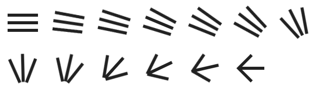
For reference, here’s what it looks like in the official Photos app.

And for spoilers, here’s where I ended up with my DrawerArrowDrawable.

Design Approach
My general thought was that if I generated curves of the endpoints of each line as they move, I can simply compute a point at parameter t along each path as the drawer slides, then just draw a line from curveA point M to corresponding curveB point N.
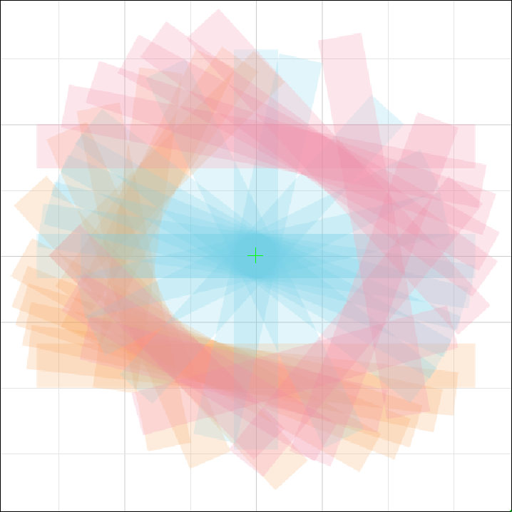
In order to generate those curves, I’d need a decent sample of datapoints to work from. I first thought that I should just captured a video off of my device of me opening the drawer and pull every N frames, but it occurred to me that the interpolator on the drawer slide would prevent those from frames from being evenly space. Instead of anything too sophisticated, I just moved the drawer in roughly even increments and captured screenshots of each step.
From there, I layered all the images in Adobe Illustrator and traced over each line with a vector line (conveniently scaled so that 6pt equaled 6px). This was a rather labor intensive process that was filled with plenty of error; after all, six pixels plus antialiasing is a comically low level of precision for the sort of math that would be coming.
From here, I dropped the stroke width way down and cleaned up the important lines so that the menu icon, halfway state, and arrow icon stages all made the perfect desired vector shapes. With this prep work done, it was merely a matter of divining the desired endpoint sweep curves.
I went through quite a few iterations of building the swept curves. At one point I even used my old copy of Rhino3D to try to interpolate the curves through the series of endpoints, but the loss of precision from the tracing was so great that a mathmatetically correct interpolation resulted in some pretty wonky curves. I settled on just using the Pen tool and a healthy dose of artistic liberty. I bolded out the drawer, halfway, and arrow stages and got to work drawing some b-splines.
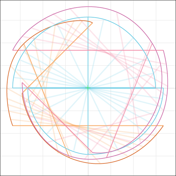
My first try at this resulted in three pairs of curves that traced the endpoints. This actually created a super minor problem that probably would have gone unnoticed by most people; the short version is that each curve wasn’t necessarily the same length, so the three lines each drawn between the midpoints (ie. 50% of the way along the curve, t = .5f) of their paired curves wouldn’t necessarily create a pixel perfect halfway state. That is to say, the middle bar would want to be completely vertical with the top and bottom bars flanking it at matching angles.
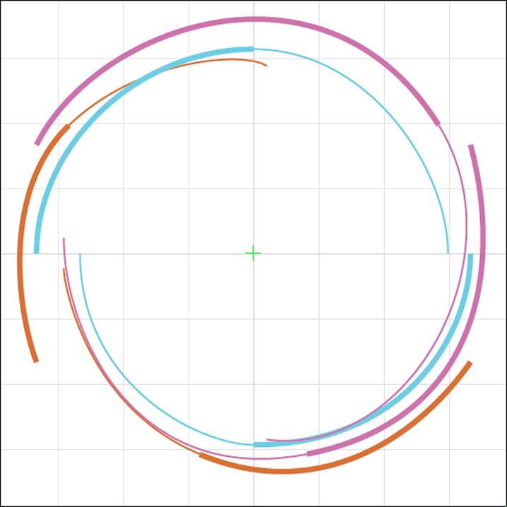
To fix this, I re-drafted the curves so that each one had exactly three control points: one at the beginning drawer icon state, on in the middle state, and one at the ending arrow state. Then, I split these compound curves into two distinct curves, one from start to middle and one from middle to end. With two “continous” curves forming one hybrid curve, I’d just make sure that when finding a point within 0-50% of the hybrid curve (regardless of its overall length), I’d look on the first curve, and when looking for a point in the 50-100% section of the hybrid curve, I’d look on the second curve; this meant that the 50% mark would be the point where these two curve meet, which I’d drafted as the endpoint in the halfway state. (If I’m not conveying this well, the image below may help. The “start to middle” 0-50% section of these curves are thicker in the picture. Its hard to tell but the thick and thin sections of the lines aren’t ever the exact same length.)
With all the vector-work complete, it was now a matter of getting from Illustrator to something useful to Android. Turns out the .svg format is pretty great for taking complex splines and turning them into a simple series of points. Here’s what two curve looks like in an .svg.
<path
    id="MIDDLE_LEFT_FIRSTHALF" fill="none" stroke="#69CCE6" stroke-width="0.25"
    d="M5.042,35C5.042,20.333,18.625,6.791,35,6.791"
    />
<path
    id="MIDDLE_LEFT_SECONDHALF" fill="none" stroke="#69CCE6" stroke-width="0.25"
    d="M35,6.791c16.083,0,26.853,16.702,26.853,28.209"
    />
How to Talk Android from Illustrator
Armed with a correctly generated series of curves in an .svg, I just needed to figure out how to turn them into Android/Java curves. For my uses, the only part of the .svg format that is important is the section contained by d="...". It holds a series of letters and coordinates that represents the origin point and the control points. This string can have a whole lot of different unique key letters, but my curves were generated such that there would only be three letters (M, C, and c).
-
M- will be followed by two values. This indicates a “move” command. As the first value, it indicates the start point of the curve with its two values. Corresponds perfectly toPath.moveTo(). -
C- will be follwed by six values (three points). This indicates a “cubic curve” command. Corresponds perfectly toPath.cubicTo(). -
c- will be follwed by six values (three points). This indicates a “cubic curve” command in relative coordinates to the previous point. Corresponds perfectly toPath.rCubicTo().
After manually parsing, the above .svg xml now looks like this in Android Path objects.
  Path first = new Path();
  first.moveTo(5.042f, 35f);
  first.cubicTo(5.042f, 20.333f, 18.625f, 6.791f, 35f, 6.791f);
  Path second = new Path();
  second.moveTo(35f, 6.791f);
  second.rCubicTo(16.083f, 0f, 26.853f, 16.702f, 26.853f, 28.209f);
Implementing the Drawable
In order to handle the way I drafted “one” curve as of two connecting curves, I created a simple JoinedPath that contains both Path objects and handled all the logic for determining which internal curve to use. I then take a pair of JoinedPath curves and construct a BridgingLine that is responsible for drawing the visible line between the two endpoint sweep curves.
  JoinedPath joinedA = new JoinedPath(first, second);
  JoinedPath joinedB = new JoinedPath(first, second);
  BridgingLinemiddleLine = new BridgingLine(joinedA, joinedB);
As outlined at the outset, the idea is that a value 0 to 1 would be used to drive the animation. This value, called parameter in my code, is used to determine the point along each JoinedPath to get for drawing the lines. Whenever parameter is updated, invalidateSelf() is called, forcing the drawable to redraw new lines based on the new parameter.
Minor implementation note: you have to wrap a Path object with a PathMeasure in order to easily grab a point at a given length along a path.
/**
 * Returns a point on this curve at the given {@code parameter}.
 * For {@code parameter} values less than .5f, the first path will drive the point.
 * For {@code parameter} values greater than .5f, the second path will drive the point.
 * For {@code parameter} equal to .5f, the point will be the point where the two
 * internal paths connect.
 */
private void getPointOnLine(float parameter, float[] coords) {
  if (parameter <= .5f) {
    parameter *= 2;
    measureFirst.getPosTan(lengthFirst * parameter, coords, null);
  } else {
    parameter -= .5f;
    parameter *= 2;
    measureSecond.getPosTan(lengthSecond * parameter, coords, null);
  }
}
With that done, drawing the line is as simple as calling BridgingLine.draw(Canvas) for each of the three BridgingLines in the drawables onDraw(Canvas) method.
/**
 * Draw a line between the points defined on the paths backing {@code measureA} and
 * {@code measureB} at the current parameter.
 */
private void draw(Canvas canvas) {
  pathA.getPointOnLine(parameter, coordsA);
  pathB.getPointOnLine(parameter, coordsB);
  canvas.drawLine(coordsA[0], coordsA[1], coordsB[0], coordsB[1], linePaint);
}
The Little Things
As you may have noticed, the drawer icon rotates from 3 o’clock to 9 o’clock when opening, and once fully extended, it rotates the rest of the way around from 9 o’clock to 3 o’clock. To do this, I added a boolean flip field and corresponding setter; its up to the DrawerListener to inform the DrawerArrowDrawable when it should flip over.
At first look, it may seem like this effect would requires another set of paths; at second glance, perhaps you’d just rotate the paths 180 degrees. It actuallys turns out the effect is achieved by simply mirroring the paths veritcally. This can be achieved very simply with the magic of negative scaling.
@Override public void draw(Canvas canvas) {
  if (flip) {
    canvas.save();
    canvas.scale(1f, -1f, getIntrinsicWidth() / 2, getIntrinsicHeight() / 2);
  }

  topLine.draw(canvas);
  middleLine.draw(canvas);
  bottomLine.draw(canvas);

  if (flip) canvas.restore();
}
The other gotcha in DrawerArrowDrawable was a perenial Android pitfall when developing on a single device: the paths are hardcoded in terms of a certain dpi. In hindsight, its super obvious: the .svg coordinates are generated from an Illustrator trace of a xxhdpi image where I scaled it to 1 pt equals 1 px. Resultingly, the output curve points are set in pixel values for xxhdpi (3px / dp). Thankfully, its a trivial matrix transform on a path to adjust to the running-device’s density.
float density = resources.getDisplayMetrics().density;
scalePath(firstPath, density);

...

/**
 * Scales the paths to the given screen density. If the density matches the
 * {@link DrawerArrowDrawable#PATH_GEN_DENSITY}, no scaling needs to be done.
 */
private static void scalePath(Path path, float density) {
  if (density == PATH_GEN_DENSITY) return;
  Matrix scaleMatrix = new Matrix();
  scaleMatrix.setScale(density / PATH_GEN_DENSITY, density / PATH_GEN_DENSITY, 0, 0);
  path.transform(scaleMatrix);
}
I also added support for rounded lines that’s pretty nifty, check the source to see how its implemented if interested.
Hooking it Up
Setting up your app to use DrawerArrowDrawable is super easy, here’s all there is to it.
final DrawerArrowDrawable drawerArrowDrawable = new DrawerArrowDrawable(resources);
getActionBar().setIcon(drawerArrowDrawable);

drawer.setDrawerListener(new DrawerLayout.SimpleDrawerListener() {
  @Override public void onDrawerSlide(View drawerView, float slideOffset) {
    // Sometimes slideOffset ends up so close to but not quite 1 or 0.
    if (slideOffset >= .995) {
      drawerArrowDrawable.setFlip(true);
    } else if (slideOffset <= .005) {
      drawerArrowDrawable.setFlip(false);
    }

    drawerArrowDrawable.setParameter(offset);
  }
});
Results
And that’s pretty much all there is to it. I’m super happy with how it turned out all things considered. There probably a simpler way, but the process for making this was a ton of fun.
Source
The source code and a little sample are uploaded here on github. Help yourself and as always, pull requests welcome.